Thermocouples - An overview
Thermocouples are indispensable in industrial processes and are suitable for wide temperature ranges. They are available as different types and are mostly used at high temperatures or in industrial furnaces. Learn more about the heat resistant temperature sensor!
Table of content
What is a thermocouple?
Thermocouples are based on the principle of comparative measurement and consist of two metallic conductors of different materials that are welded together at the tip. Depending on the material pairing, they have different levels of thermoelectric voltage and are suitable for different temperature ranges. The most commonly used are thermocouples type K and thermocouples type J.
How is a thermocouple constructed?
Normally, the thermocouple consists of a combination of two materials with diameters ranging from 0.2 to 5 mm. When using noble materials such as rhodium or platinum, these dimensions range from 0.1 to 0.5 mm. When selecting a thermocouple material, care should be taken to ensure that it has a high Seebeck factor and that temperature affects its value as little as possible in order to achieve a linear characteristic. The appropriate thermocouple material is selected according to the range of the measured temperature.
The probe's casing is exposed to very high temperatures, so it is necessary to use different types of steel. At the highest temperatures, the thermocouple protection tube is made of heat-resistant steel or ceramic materials. The thermowell must be resistant to corrosion, thermal shock and mechanical damage. A desirable feature to prevent corrosion of the thermocouple is the impermeability of gases that could significantly accelerate the aging process of the thermocouple. There are also designs without a cover that are used to reduce dynamic errors. For special measurements, such as the temperature of liquid metals, glass or liquid steel, highly specialized thermocouple designs are used.
What properties should a thermocouple have?
The thermowell must be resistant to corrosion, thermal shock and mechanical damage. A desirable feature to prevent corrosion of the thermocouple is the impermeability of gases that could significantly accelerate the aging process of the thermocouple. Designs without a cover can be used to reduce dynamic errors.
Also, when selecting a thermocouple material, care should be taken to ensure that it has a high Seebeck factor and that temperature affects its value as little as possible to achieve a linear characteristic.
How do thermocouples and resistance thermometers differ?
In contrast to a resistance thermometer, a thermocouple can be used in a much higher temperature range. In addition, thermocouples are more robust and resistant to mechanical stress.
What are the metal combinations for thermocouples?
From the large number of possible metal combinations, certain ones have been selected and their properties standardized, in particular the voltage series and the permissible limit deviations. The following elements are standardized worldwide (IEC) as well as European or nationally with regard to the thermoelectric voltage and its tolerance.
Colour coding for thermocouples
|
Element |
Maximum temperature |
Defined until |
Plus leg |
Minus leg |
|
|
Fe-CuNi |
„J“ |
750°C |
1200°C |
black |
white |
|
Ce-CuNi |
„T“ |
350°C |
400°C |
brown |
white |
|
NiCr-Ni |
„K“ |
1200°C |
1370°C |
green |
white |
|
NiCr-CuNi |
„E“ |
900°C |
1000°C |
purple |
white |
|
NiCrSi-NiSi |
„N“ |
1200°C |
1300°C |
pink |
white |
|
Pt10Rh-Pt |
„S“ |
1600°C |
1540°C |
orange |
white |
|
Pt13Rh-Pt |
„R“ |
1600°C |
1760°C |
orange |
white |
|
Pt30Rh-Pt6Rh |
„B“ |
1700°C |
1820°C |
gray |
white |
|
Thermocouples according to DIN EN 60 584 |
|||||
|
Element |
Maximum temperature |
Defined until |
Plus leg |
Minus leg |
|
|
Fe-CuNi |
„L“ |
700°C |
900°C |
red |
blue |
|
Ce-CuNi |
„U“ |
400°C |
600°C |
red |
brown |
|
Thermocouples according to DIN 43 710 |
|||||
Colour coding of compensating cables
|
Element |
Type |
Mantle |
Plus leg |
Minus leg |
|
Cu-CuNi |
„T“ |
brown |
brown |
white |
|
Fe-CuNi |
„J“ |
black |
black |
white |
|
NiCr-Ni |
„K“ |
green |
green |
white |
|
NiCrSi-NiSi |
„N“ |
pink |
pink |
white |
|
NiCr-CuNi |
„E“ |
purple |
purple |
white |
|
Pt10Rh-Pt |
„S“ |
orange |
orange |
white |
|
Pt13Rh-Pt |
„R“ |
orange |
orange |
white |
|
Colour coding for elements according to DIN EN 60 584 |
||||
|
Element |
Type |
Mantle |
Plus leg |
Minus leg |
|
Fe-CuNi |
„L“ |
blue |
red |
blue |
|
Ce-CuNi |
„U“ |
brown |
red |
brown |
|
Colour coding for elements according to DIN 43 713 |
||||
|
Element |
Type |
Mantle |
Plus leg |
Minus leg |
|
NiCr-Ni |
„K“ |
green |
red |
green |
|
Pt10Rh-Pt |
„S“ |
white |
red |
white |
|
Pt13Rh-Pt |
„R“ |
white |
red |
white |
|
Colour coding for elements according to DIN 43 714, Status 1979 |
||||

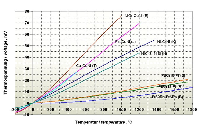
Voltages of different thermocouples relative to a reference temperature of 0 °C according to DIN EN 60584
How does a thermocouple work?
The principle of thermocouples is the result of the so-called Seebeck effect. This phenomenon can be explained by the theory of free electrons, according to which different types of conductors have a different density of free electrons. At the contact point of two different conductors forming a thermocouple, electrons will move from one conductor to the other. A larger number of electrons will move from a higher density conductor to a lower density conductor. The intensity of electron migration depends on the temperature of the contact point of the two conductors, it is also higher the higher the temperature. The electromotive force formed in a thermocouple circuit consisting of two different conductors whose ends have been placed at different temperatures is given by the formula:
V=(S-SA)⋅(T2-T1)
The resulting electromotive force is on the order of a few to several dozen microvolts per degree Celsius.

Example measuring chain thermocouple
How to choose the right thermocouple?
The choice of thermocouple type depends primarily on the operating temperature. Furthermore, an element with a high thermoelectric voltage should be selected in order to obtain a measurement signal that is as insensitive to interference as possible. In the following table: Properties of Thermocouples the different elements are listed together with a short characterization. The recommended maximum temperatures can only be assumed as basic values, as they depend strongly on the application conditions. They refer to a wire diameter of 3 mm for the base and 0.5 mm for the noble elements.
|
Cu-CuNi |
350°C |
Little spread. |
|
Fe-CuNi |
700°C |
Widely used, inexpensive, susceptible to corrosion. |
|
NiCr-CuNi |
700°C |
Low spread, high thermoelectric voltage. |
|
NiCr-Ni |
1000°C |
Often used in the range 800 - 1000°C, also suitable for the lower temperature range. |
|
NiCrSi-NiSi |
1300°C |
(Still) little widespread. Can partially replace noble elements. |
|
Pt10Rh-Pt |
1500°C (1300°C) |
High costs, very good long-term consistency, closely tolerated. |
|
Pt30Rh-Pt6Rh |
1700°C |
High costs, lowest thermovoltage, high maximum temperature. |
How to connect a thermocouple?
The length of the thermocouple or compensation cable is of secondary importance due to the low internal resistance. However, for longer cable lengths with a small cross-section, the resistance of the thermocouple or compensating cable can assume comparatively high values. In order to avoid display errors, the internal resistance of the input circuit of slave devices must be at least 1000 times greater than the resistance of the connected thermocouple. Only compensating cables of the same material as the element itself or with the same thermoelectric properties may be used, otherwise a new element will be created at the junction. The compensating cable must be laid up to the reference junction. When connecting thermocouples, the polarity must be observed.
What do you do in the event of a short circuit or an interruption?
A thermocouple does not supply voltage if the measuring temperature is equal to the reference junction temperature. If a thermocouple or the compensating cable is short-circuited, the new measuring point is created at the location of the short-circuit. If such a short-circuit occurs, for example in the connection head, the temperature of the actual measuring point is no longer displayed, but that of the connection head. If there is an interruption in the measuring circuit, the subsequent device displays the reference junction temperature.
- ${title}${badge}


